7.12 Contact
RULE NO. |
DESCRIPTION |
LAYOUT RULE |
Layer |
CO = Contact |
|
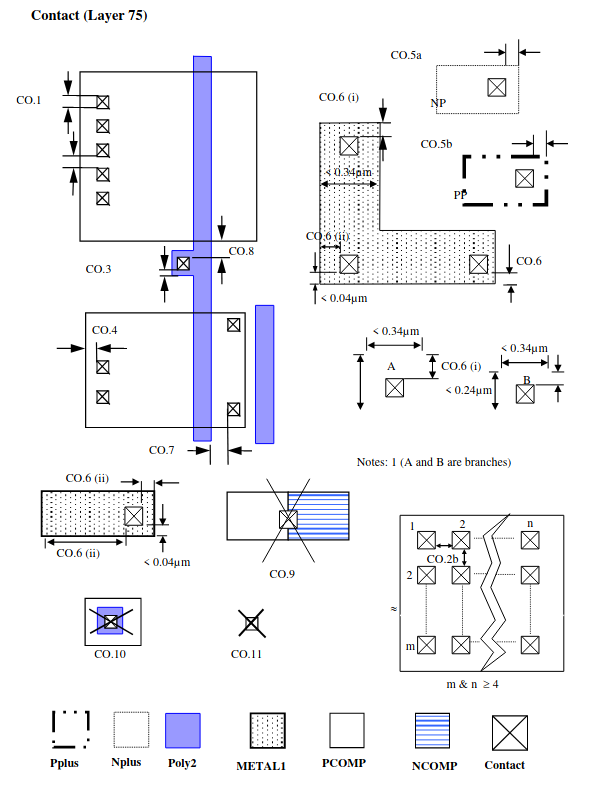
CO.1 |
Min/max contact size |
0.22 |
CO.2a |
Space |
0.25 |
CO.2b |
Space in 4x4 or larger contact array |
0.28 |
CO.3 |
Poly2 overlap of contact |
0.07 |
CO.4 |
COMP overlap of contact |
0.07 |
CO.5a |
Nplus overlap of contact on COMP (Only for contacts to butted Nplus and Pplus COMP areas) |
0.1 |
CO.5b |
Pplus overlap of contact on COMP (Only for contacts to butted Nplus and Pplus COMP areas) |
0.1 |
CO.6 |
Metal1 overlap of contact I) Metal1 (< 0.34μm) end-of-line overlap (1) II) If Metal1 overlaps contact by < 0.04μm on one side, adjacent metal1 edges overlap III) Minimum Metal1 overlap of contact on all sides for minimum contact resistance variation* (guideline) |
0.005 0.06 0.06 0.12 |
CO.7 |
Space from COMP contact to Poly2 on COMP |
0.15 |
CO.8 |
Space from Poly2 contact to COMP |
0.17 |
CO.9 |
Contact on NCOMP to PCOMP butting edge is forbidden (contact must not straddle butting edge) |
|
CO.10 |
Contact on Poly2 gate over COMP is forbidden. |
|
CO.11 |
Contact on field oxide is forbidden. |
Note
Note
Applies to all < 0.34μm wide metal lines, excluding metal branches shorter than 0.24μm.
For better yield and reliability try to avoid single contacts on any layer.