13.3 Design rules for Dummy Metal addition
For good metal etch process margin, a minimum metal density is recommended for Metaln and MetalTop. Device (circuit) layouts that does not meet minimum pattern density rule (stated in the metal design rules) shall be added in the dummy metal patterns. Dummy metals are added to improve the overall metal density so as to reduce the potential dishing issue due to CMP also.
Generation method:
Check the metal density in an area of 200um by 200um at a step of 100um.
Add dummy metal if total die metal density is less than 30%
Dummy metal size: 2.0um x 2.0 um; space is 1.2um
Please follow the following table when generating the Dummy metals:
RULE NO. |
DESCRIPTION |
LAYOUT GUIDELINE |
Layer |
DMF – Dummy Metal Fill |
|
Use PMNDMY mark layer to exclude dummy metal generation in certain critical analog/RF areas. |
||
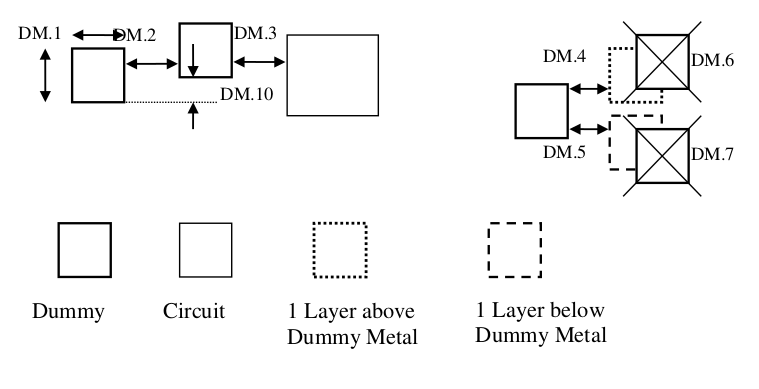
DM.1 |
Min/Max Dummy metal line width/length |
2.0 um |
DM.2a* |
Min Dummy metal line space (for Layout) |
1.2 um |
DM.2b |
Min Dummy metal line space (for DRC) |
0.98um |
DM.2c |
Min Dummy metal line space for thick top metal (3um Top metal) |
2.0um |
DM.3 |
Minimum space between dummy metal and circuit Metal line |
2.0um |
DM.4 |
Dummy Metal space to Subsequent Metal layer (E.g. Dummy M1 space to M2) |
1um |
DM.5 |
Dummy Metal space to Previous Metal layer (E.g. Dummy M2 space to M1; Dummy M1 space to Poly2) |
1um |
DM.6 |
No overlap of Dummy Metal with the Subsequent Metal layers |
|
DM.7 |
No overlap of Dummy Metal with the Previous layers |
|
DM.8 |
There should not be any dummy metal pattern fill in the following areas
Space from these Structures |
6um |
DM.9* |
Do not use exact replicates of dummy metal fill patterns for consecutive metal layers to avoid dielectric and metal stress problems? E.g. the Metal4 dummy metal fill patterns should not be an exact copy of the Metal3 dummy fill pattern. (Offsets value:) |
0.5um |
DM.10* |
Offset between the Dummy metal of the same layers |
0.5um |
Note