13.2 Design rules for Dummy Poly2 addition
Dummy Poly2 Generation is recommended to customer prime die, which does not meet GlobalFoundries Specification for minimum poly2 GDS density (stated under Poly2 rules). Minimum poly2 density is required to ensure good process control of device channel length across chip. No dummy poly2 generation is required for prime die that meets poly2 density specification. Non-functional dummy poly2 features are added over dummy COMP feature with constrains described by the rules below.
This dummy poly2 generation shall be applied, if poly2 total pattern density is less than 14%. It shall be preferably placed at most empty space.
RULE NO. |
DESCRIPTION |
LAYOUT RULE |
For Drawing / For DRC |
Layer |
DPF – Dummy Poly2 Fill |
||
Use PMNDMY mark layer to exclude dummy Poly2 generation in Certain critical analog/RF areas. |
|||
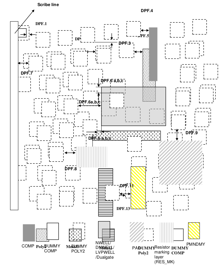
DPF.1 |
Dummy Poly2 is generated on top of dummy COMP by sizing up the Dummy COMP by 0.3um per side. The size of the dummy poly2 is 5.6 umX 5.6um square, and generated in prime die (1). |
For Drawing |
|
DPF.2a* |
Space between dummy poly2 (for drawing algorithm). |
2.4 |
For Drawing |
DPF.2b |
Resulted minimum space between Dummy poly in all directions (for DRC check) |
1.1 |
For DRC Check |
DPF.3* |
Stagger both X and Y direction |
1.6 |
For Drawing |
DPF.4 |
Space of dummy poly2 to COMP |
3.2 |
For DRC |
DPF.5 |
Space of dummy poly2 to poly2 |
5 |
For DRC |
DPF.6a |
Space of dummy poly2 to Nwell boundary |
1 |
For DRC |
DPF.6b |
Space of dummy poly2 to DNWELL boundary |
2 |
For DRC |
DPF.6c |
Space of dummy poly2 to LVPWELL boundary |
1 |
For DRC |
DPF.6d |
Space of dummy poly2 to Dualgate boundary |
1 |
For DRC |
DPF.7* |
Space from dummy poly2 in prime die to scribe line |
25.7 |
For DRC |
DPF.8 |
Space from dummy poly2 to Resistor marking layer (RES_MK). |
19.7 |
For DRC |
DPF.9 |
Space of dummy poly2 to Pad |
6.7 |
For DRC |
DPF.10* |
Remove truncated dummy squares |
For DRC |
|
DPF.11 |
Space to dummy COMP exclude layer |
29.7 |
For DRC |
DPF.12 |
Space of dummy poly2 fill to active circuit metal1 (2) |
2 |
For DRC |
DPF.13 |
Space of dummy poly2 fill to active circuit metal2 (2) |
2 |
For DRC |
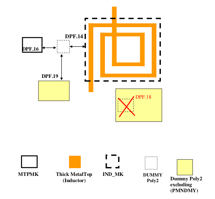
DPF.14 |
Minimum dummy poly2 space to IND_MK layer |
3 |
For DRC |
DPF.15 |
Dummy poly2 should not exist under IND_MK layer |
For DRC |
|
DPF.16 |
Minimum dummy poly2 space to MTPMARK layer |
3 |
For DRC |
DPF.17 |
Dummy poly2 should not exist under MTPMARK layer |
For DRC |
|
DPF.18 |
Dummy poly2 cannot exit under the marking layer “PMNDMY” |
For DRC |
|
DPF.19 |
Space from dummy poly2 to dummy poly2 excluding layer (PMNDMY) (2) |
8 |
For DRC |
Note
Dummy Poly2 is only generated in the prime die.
DPF.12 and DPF.13 do not apply to dummy metal fill.