14.6.3 Metal Slotting rules
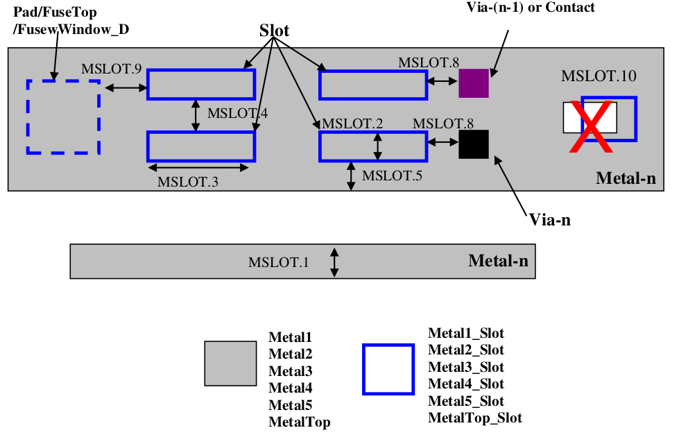
Use Metal1_Slot, Metal2_Slot, Metal3_slot, Metal4_Slot, Metal5_Slot and MetalTop_Slot (slot mark layers) to identify respective metal layer slotting area. These layers will be used to create the slots automatically (by logic operation) and there is no need to create physical holes (slots) in the routing metal lines. Below rule shall be followed for metal slotting layout.
RULE NO. |
DESCRIPTION |
LAYOUT RULE |
MSLOT.1 |
Maximum metal width without slotting |
30 |
MSLOT.2 |
Minimum slot width (slot mark layers) |
2 |
MSLOT.3 |
Slot length (slot mark layers) |
|
|
10 |
|
|
250 |
|
MSLOT.4 |
Slot space (slot mark layers) |
|
|
10 |
|
|
30 |
|
MSLOT.5 |
Minimum slot (slot mark layers) to metal edge spacing |
10 |
MSLOT.6 |
For multiple slots that spans the metal width, slots should be staggered. |
|
MSLOT.7 |
Minimum space from via-n to metal-n slot |
0.2 |
MSLOT.8 |
Minimum space from via-(n-1) / contact to metal-n slot |
0.2 |
|
||
|
||
|
||
|
||
|
||
Minimum distance to these layers |
5 |
|
MSLOT.10 |
Slot mark layer on the metal hole (same metal level, e.g. Metal1_Slot on the Metal1 hole) are not allowed |