12.2 Six Metal Scribe Line Guard Ring Structure
The contact and via rings should consist of the minimum size contacts/vias placed in staggered formation with separation of 0.7µm within each of the rings defined by the coordinates in the table below. X=0 defines the inner (die-side) edge of the guard ring structure. The guardring structure has been divided into two groups based the packaging process difference. The guard ring in the product uses solders bumping flip-chip need to be protected from chemical attack during solder bumping process.
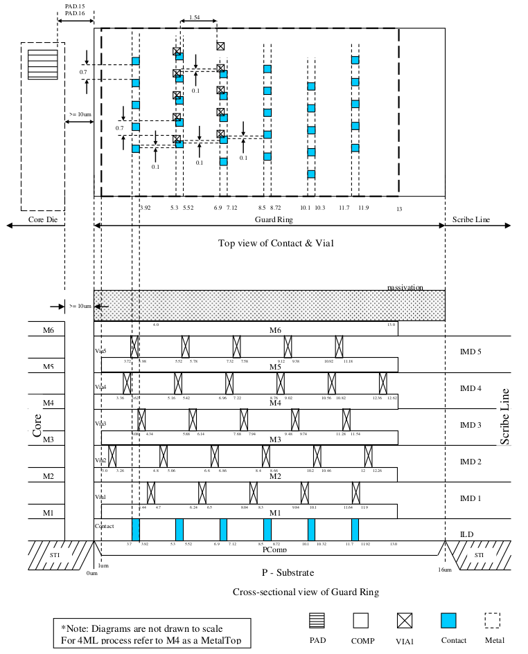
This diagram is a schematic describing scribe line guard ring layer for COMP, CONT, Via1 & Metal only. For detailed scribe line guard ring layout, please refer to following table.
Ring |
Starting Coordinate |
Ending Coordinate |
Size (μm) |
PCOMP |
0 |
16 |
16 |
GUARD_R ING_MK |
0 |
16 |
16 |
AD |
0 |
16 |
16 |
Contact |
3.7 |
3.92 |
0.22 |
Contact |
5.3 |
5.52 |
0.22 |
Contact |
6.9 |
7.12 |
0.22 |
Contact |
8.5 |
8.72 |
0.22 |
Contact |
10.1 |
10.32 |
0.22 |
Contact |
11.7 |
11.92 |
0.22 |
Metal1 |
1 |
13 |
12 |
Via1 |
4.44 |
4.7 |
0.26 |
Via1 |
6.24 |
6.5 |
0.26 |
Via1 |
8.04 |
8.3 |
0.26 |
Via1 |
9.84 |
10.1 |
0.26 |
Via1 |
11.64 |
11.9 |
0.26 |
Metal2 |
0 |
13 |
13 |
Via2 |
3 |
3.26 |
0.26 |
Via2 |
4.8 |
5.06 |
0.26 |
Via2 |
6.6 |
6.86 |
0.26 |
Via2 |
8.4 |
8.66 |
0.26 |
Via2 |
10.2 |
10.46 |
0.26 |
Via2 |
12 |
12.26 |
0.26 |
Metal3 |
1 |
13 |
12 |
Via3 |
4.08 |
4.34 |
0.26 |
Via3 |
5.88 |
6.14 |
0.26 |
Via3 |
7.68 |
7.94 |
0.26 |
Via3 |
9.48 |
9.74 |
0.26 |
Via3 |
11.28 |
11.54 |
0.26 |
Metal4 |
0 |
13 |
13 |
Via4 |
3.36 |
3.62 |
0.26 |
Via4 |
5.16 |
5.42 |
0.26 |
Via4 |
6.96 |
7.22 |
0.26 |
Via4 |
8.76 |
9.02 |
0.26 |
Via4 |
10.56 |
10.82 |
0.26 |
Via4 |
12.36 |
12.62 |
0.26 |
Metal5 |
1 |
13 |
12 |
Via5 |
3.72 |
3.98 |
0.26 |
Via5 |
5.52 |
5.78 |
0.26 |
Via5 |
7.32 |
7.58 |
0.26 |
Via5 |
9.12 |
9.38 |
0.26 |
Via5 |
10.92 |
11.18 |
0.26 |
MetalTop |
0 |
13 |
13 |
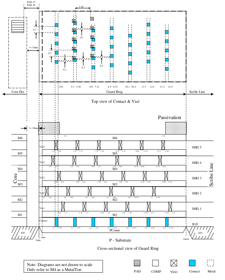
This diagram is a schematic describing scribe line guard ring layer for COMP, CONT, Via1 & Metal only. For detailed scribe line guard ring layout, please refer to following table.
Ring |
Starting Coordinate |
Ending Coordinate |
Size (μm) |
PCOMP |
0 |
16 |
16 |
GUARD_RING_MK |
0 |
16 |
16 |
AD |
0 |
16 |
16 |
Contact |
3.7 |
3.92 |
0.22 |
Contact |
5.3 |
5.52 |
0.22 |
Contact |
6.9 |
7.12 |
0.22 |
Contact |
8.5 |
8.72 |
0.22 |
Contact |
10.1 |
10.32 |
0.22 |
Contact |
11.7 |
11.92 |
0.22 |
Contact |
13.3 |
13.52 |
0.22 |
Metal1 |
1 |
16 |
15 |
Via1 |
4.44 |
4.7 |
0.26 |
Via1 |
6.24 |
6.5 |
0.26 |
Via1 |
8.04 |
8.3 |
0.26 |
Via1 |
9.84 |
10.1 |
0.26 |
Via1 |
11.64 |
11.9 |
0.26 |
Via1 |
13.44 |
13.7 |
0.26 |
Metal2 |
0 |
16 |
16 |
Via2 |
3 |
3.26 |
0.26 |
Via2 |
4.8 |
5.06 |
0.26 |
Via2 |
6.6 |
6.86 |
0.26 |
Via2 |
8.4 |
8.66 |
0.26 |
Via2 |
10.2 |
10.46 |
0.26 |
Via2 |
12 |
12.26 |
0.26 |
Metal3 |
1 |
16 |
15 |
Via3 |
4.08 |
4.34 |
0.26 |
Via3 |
5.88 |
6.14 |
0.26 |
Via3 |
7.68 |
7.94 |
0.26 |
Via3 |
9.48 |
9.74 |
0.26 |
Via3 |
11.28 |
11.54 |
0.26 |
Via3 |
13.08 |
13.34 |
0.26 |
Metal4 |
0 |
16 |
16 |
Via4 |
3.36 |
3.62 |
0.26 |
Via4 |
5.16 |
5.42 |
0.26 |
Via4 |
6.96 |
7.22 |
0.26 |
Via4 |
8.76 |
9.02 |
0.26 |
Via4 |
10.56 |
10.82 |
0.26 |
Via4 |
12.36 |
12.62 |
0.26 |
Metal5 |
1 |
16 |
15 |
Via5 |
3.72 |
3.98 |
0.26 |
Via5 |
5.52 |
5.78 |
0.26 |
Via5 |
7.32 |
7.58 |
0.26 |
Via5 |
9.12 |
9.38 |
0.26 |
Via5 |
10.92 |
11.18 |
0.26 |
Via5 |
12.72 |
12.98 |
0.26 |
MetalTop |
0 |
16 |
16 |
Pad |
4 |
13 |
9 |